It’s time for me to document how I wire and test simple mechanical endstops. This is the fourth time I do this, I’ve installed endstops on two Prusa Mendels (i2), on my steel adapto and this time I’m installing them on an aluminium frame single plate Prusa i3.
Reprap FAQ #1
Q: Help! My reprap only moves in one direction!
A: Fix your endstops!
This is by far the most common question I hear from (impatient) new reprappers. If your endstops are misconfigured, installed incorrectly or (most usually) missing most firmware will by default limit the effected axes to only move away from the endstops. It is MUCH easier to just install endstops than to disable them in firmware.
Parts and Equipment

You will need
- 3 mechanical endstops, mine are the bare bones kind without any PCB or fancy LEDs.
- Three wire endstop plugs (two wire also work fine). Mine came with my ramps and wiring kit, the wires are 26AWG. If you’re looking to make your own I think the plugs are called 3×1 Dupont pin headers and are .1″ (ugh, inches, that’s 2.54mm).
- Optional cable wrap to make them look nicer.
- Printed endstop holders
- Six M2.5 x 16mm machine screws with nuts and washers or zip ties or glue (hot glue should work nicely) to attach the endstops to the endstop holders. If you use glue it has to work on whatever plastic your parts are printed in, cyanoacrylate (super glue) does not always work on PLA.
- Soldering equipment and basic tools.
- Reprap electronics (I used RAMPS) with firmware installed. Marlin or Sprinter are the ones I’ve used.
Background
Useful information about endstops can be found at http://reprap.org/wiki/Mechanical_Endstop and http://forums.reprap.org/read.php?13,64189
I find mechanical endstops more than good enough for reprap use. Opto endstops (I hear) are prone to errors and fail easily from stray light beams. Hall sensor endstops http://reprap.org/wiki/Hall-%CE%98 are high tech but cost more and I’ve never felt the need to test them (donate a set to me if you want me to!).
My endstops have three connectors. They are marked C (common), NC (normally closed) and NO (normally open). You can connect all three or C and one of NC and NO. I recommend always connecting NC. This is because with NC there is a circuit with signal through it while the reprap is running and not at the endstop. If for any reason the circuit is broken (wire fails or falls off etc.) the endstop is triggered and the reprap should stop (or at least stop moving towards the endstop). Endstops are very simple switches that connect either NC or NO to C depending on whether the switch is triggered or not.
RAMPS has six connectors for endstops, max and min each for X, Y and Z. I recommend only using min endstops and using software endstops (in firmware) to limit movement at the other end of each axis. The endstop pins are grouped on the top right of RAMPS and are clearly marked endstops, X-, Y- and Z- (these are the min endstops, the equivalent max endstops pins aren’t marked and are between/after these). Each has three pins marked S, –, +.
WARNING!
If you connect the endstops incorrectly you will end up sending 5V up the USB data line to your computer. This is easily done if you plug the 3-pin plug in reversed. I don’t think this is dangerous (it’s just a signal, not a lot of power) and I also think the USB port is supposed to handle this kind of thing but it will give your computer an error and you will lose the USB port (COM port on windows, /dev/ttyACM0 or similar on linux).
If you get this wrong on linux run dmesg, you should see an error message maybe something like
[10025599.475353] usb 3-3: USB disconnect, device number 4
On Windows the COM port just vanishes (for me at least) with no error message or anything but pronterface won’t/can’t connect to ramps. If the plugs are wired correctly this is fixed by reversing the endstop plug (your computer might need some time or reconnecting the USB plug to rediscover the port).
What goes where?
Common on the endstop goes to S on ramps and NC goes to minus. With my equipment this is the whole setup:
switch     ramps     wires
1    C      S     blue
2    NC     -     black
3    NO     +     red
The numbers aren’t arbitrary, they are printed on the switch on the corresponding reverse side from NC etc.
Test with firmware first
If you aren’t sure of what goes where or which connector is which on your endstops it’s easy enough to test. Make sure you have marlin installed and that your endstops are set up correctly. In short near https://github.com/ErikZalm/Marlin/blob/Marlin_v1/Marlin/Configuration.h#L231 you want
#define ENDSTOPPULLUPS
// The pullups are needed if you directly connect a mechanical endswitch between the signal and ground pins.
const bool X_MIN_ENDSTOP_INVERTING = false; // set to true to invert the logic of the endstop.
const bool Y_MIN_ENDSTOP_INVERTING = false; // set to true to invert the logic of the endstop.
const bool Z_MIN_ENDSTOP_INVERTING = false; // set to true to invert the logic of the endstop.
const bool X_MAX_ENDSTOP_INVERTING = false; // set to true to invert the logic of the endstop.
const bool Y_MAX_ENDSTOP_INVERTING = false; // set to true to invert the logic of the endstop.
const bool Z_MAX_ENDSTOP_INVERTING = false; // set to true to invert the logic of the endstop.
#define DISABLE_MAX_ENDSTOPS
Marlin inverts the logic of endstops by default, a pitfall that easily catches the unwary.

Plug in one of your endstop wires to one of the minimum endstop pins (I used X- in the picture) and hook the wires into the endstop (without soldering). Connect to ramps and marlin with pronterface (or whatever host software you prefer) and using the send box at the bottom right (or a custom button with “Endstops” M119, see https://t00tiereprap.wordpress.com/2013/03/13/custom-buttons-in-pronterface/ ) send M119, the gcode command to check endstops. Depress the little lever on the endstop and send M119 again. You should see the status change on the endstop that is plugged in.
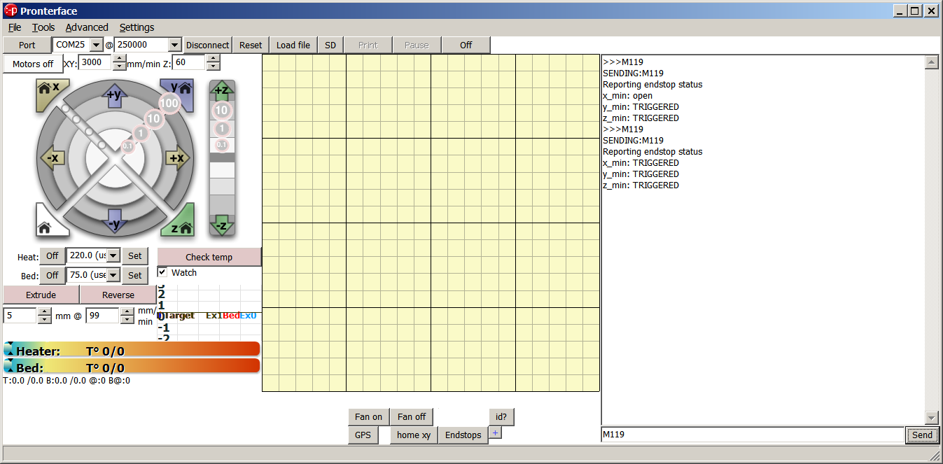
You can see that x_min went from open to TRIGGERED. Note the wire colours and orientation of the plug in ramps. If I hadn’t changed X_MIN_ENDSTOP_INVERTING in marlin these would be reversed.
Soldering the wires
Before soldering you might want to measure how long your wires should be and cut them to length. I usually just leave the full 1m of wire on and have loose wires in a bundle near ramps.

Fix the endstop in your third hand, bend the ends of the wires and hook them into the correct connectors. Solder each wire in place.

I don’t use heatshrink here but you can insulate the connectors if you want to. Optionally use 6mm spiral cable wrap around the wires for a prettier look and easier cable management.

The spiral cable wrap is tedious to install, I want to try a different kind to see if that’s any easier.
M3 screws will not fit in the holes in endstops. I’ve tried measuring and suspect that the holes and spacing are in inches (urk, http://theoatmeal.com/pl/senior_year/science ) but M2.5 screws fit. These are hard to find even here in metric country but I ordered 16mm long ones online, luckily they’re cheap. I like using screws to attach the endstops to endstop holders (these are from the i3 github repo https://github.com/josefprusa/Prusa3/blob/master/box_frame/extras/endstop-holder.scad ). Test where you want to install your endstops to choose optimal placement and orientation on the holders.

Testing placement on my alu i3, the Y endstop goes at the rear, see https://t00tiereprap.wordpress.com/2013/04/06/000-where-is-the-origin/ for how and why to place them.
The corner of the nateplate will hit the switch nicely!

thank you soo much for this tutorial!
Was pulling my hari out on how to do this one,
and searched google for quite some time as a first time rep-rap’er
very good information you have on this page!
Alex
Tq for informative article.
Do you have any photos as to where the other 2 are installed ?
Thank you for this information. Do u have a tutorial on enabling and wiring an auto leveling sensor?
Sorry no, I have never done that.